Information about H-Bridge
Information about H-Bridge
H-Bridge module L298N 2A Dual motor driver module with PWM control
An H-bridge is a simple circuit that lets you control a DC motor to go backward or forward.
You normally use it with a microcontroller, such as an Arduino, to control motors.
When you can control two motors to go either forward or backward – you can build yourself a robot!
H-Bridge concept
Here’s the concept of the H-bridge:
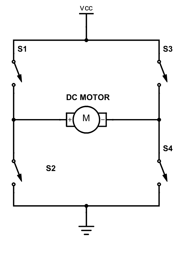
A DC motor spins either backward or forward, depending on how you connect the plus and the minus.
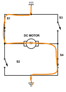
If you close switch 1 and 4, you have plus connected to the left side of the motor and minus to the other side. And the motor will start spinning in one direction.
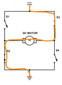
If you instead close switch 2 and 3, you have plus connected to the right side and minus to the left side. And the motor spins in the opposite direction.
The H-Bridge circuit
You can build an H-bridge with four transistors.
If you’re not sure how the transistor works, I recommend you read the article How Transistors Work first. From there you’ll learn that the transistor can work as a switch that you can open and close with the voltage on the base.
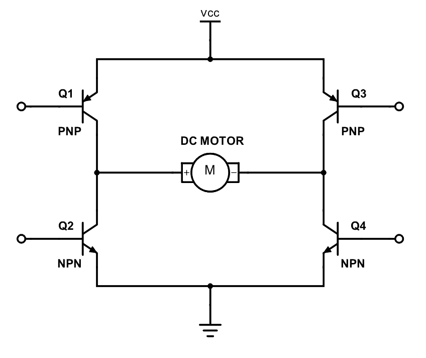
Since the transistor can be a switch, you’ll be able to make the motor spin in either direction by turning on and off the four transistors in the circuit above.
Usually, you control the transistors from a microcontroller, such as Arduino.
What Transistors To Use?
The transistors you choose must:
- Handle enough current
- Use PNP (or pmos) at the top
- Have a low voltage drop between collector and emitter
Current
The most important thing is that all the transistors can handle enough current for the motor. Otherwise it will burn out.
For example, if the motor draws 1 Ampere of current, you need transistors that can handle a minimum of 1 Ampere.
PNP (or pmos) transistors at the top
Next, you see I have chosen PNP transistors on the top, and NPN transistors on the bottom.
What turns the transistor on or off is the voltage difference between the base and the emitter.
With PNP transistors at the top, you can use a higher voltage for VCC than you use for the base of the transistors.
For example, you can use 3.3V outputs from a microcontroller and 9V for Vcc.
That won’t work if you have NPNs at the top since the emitter will be 0.7V lower than the base. Because that turns into 3.3V – 0.7V = 2.6V at the positive side of the motor, no matter what VCC voltage you choose.
Low voltage drop between collector and emitter
While building a robot in Colombia, I tried to make this circuit using TIP120 and TIP127 transistors.
That did not work.
TIP12x transistors give a 2V drop from the emitter to collector.
In such a configuration, you’d end up with a loss of 4V over the transistors. I was trying to connect this to an Arduino, using its 5V supply, but failed because it was only 1V left for the motor!
Here’s a nice article/rant about the topic: Stop using antique parts!
Basically, it says that the TIP transistors are antiques that you shouldn’t use anymore exactly because of this huge voltage drop.
Choose transistors with low voltage drop. For example BD135/BD136 or MOSFET transistors.
Protection diodes and PWM mode
A side-effect of how a motor works is that the motor will also generate electrical energy. When you disable the transistors to stop running the motor, this energy needs to be released on some way.
If you add diodes in the reverse direction for the transistors, you give a path for the current to take to release this energy. Without them, you risk that the voltage rises and damages your transistors.
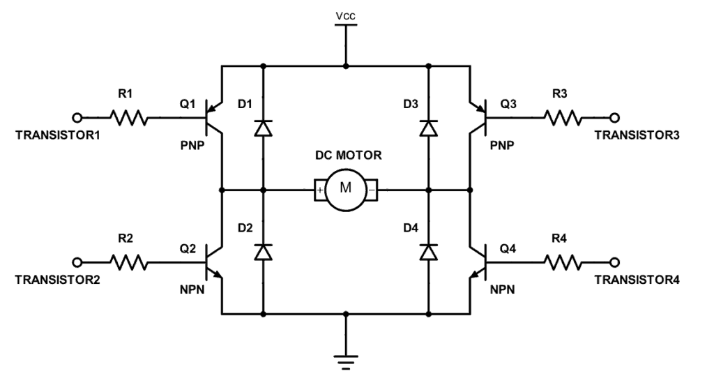
You can read more about this – and what to keep in mind if you want to use a PWM signal to control the speed of the motor, this article.
The resistors going into each base is there to reduce the current to each transistor. Not sure how to calculate it? If you’re using a microcontroller to control them, start with 1k and adjust if that doesn’t work.

Comments
Post a Comment